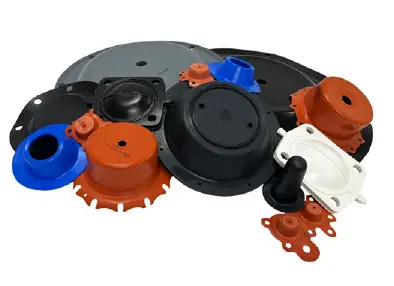
The Class 4 diaphragm is the most common design and offers economical hardware design. It was developed for installation in mechanisms which have flat mating surfaces between the cylinder and its cap or bonnet. In these cases the flange of the diaphragm serves primarily as a gasket to prevent leakage at these parting surfaces. The flanges can be perforated during manufacture to accommodate through bolts. Similarly, the periphery of the flange can be trimmed to match almost any configuration of the mating parts.
Class 4 diaphragms can be used to seal high pressures since the fabric overlay is in intimate contact with the clamped metal surfaces, thus providing secure retention across a large sealing surface.
The forces which act upon the flange joint are complex and variable. In general, flange pressure loading is determined by: internal pressures, operating temperature and environmental liquid and gases. The actual flange loading pressure required to provide adequate sealing effects has generally been found to be on the order of 1000 psi across the sealing area of the flange. If this pressure is seriously exceeded, excess elastomer flow may result, causing eventual damage to the rolling diaphragm.
The clamping flange surface should be flat over its contacting area and should not distort under applied bolt loads.
Improved flange retention can be achieved by using a rough machined hardware finish at the flange clamping area, provided no sharp edges are created which would tend to cut the elastomeric surface. A series of concentric “V” grooves spaced approximately 1/32” apart at a depth of 0.006” is suggested for retention under extremely high pressure, or with extra wide convolution applications where flange pullout forces are large.
In Class 4 designs, the convolution is formed by inverting the top head corner radius during installation. In order to keep the piston corner radius from re-inverting during operation, a curved lip retainer plate is recommended.


